
UMSAE Formula Electric PCB Design
Electric Polar Bear Racing 2024 (ePBR24) was manufactured in a condensed 8-week period. With the design, manufacturing, and troubleshooting experience that our team has gained from ePBR24, the next-generation vehicle (ePBR25) is being designed based on the improvements needed from last year’s car. This vehicle will have improved sensors to validate our simulations. A large part of this work is electrical hardware design with custom team-designed and built printed circuit boards (PCBs); these PCBs make up the circuitry system on our car.
The circuitry system is divided into two major systems: the Accumulator Control Unit (ACU) and the Vehicle Control Unit (VCU). The ACU includes all the circuitry behind the firewall (a fireproof barrier that separates the driver from the accumulator and all Tractive System (TS) Voltage). In contrast, the VCU includes all the circuitry in front of the firewall. The ACU controls all the auxiliary functions for the accumulator (safety and control) and manages/distributes low voltage (LV) power.
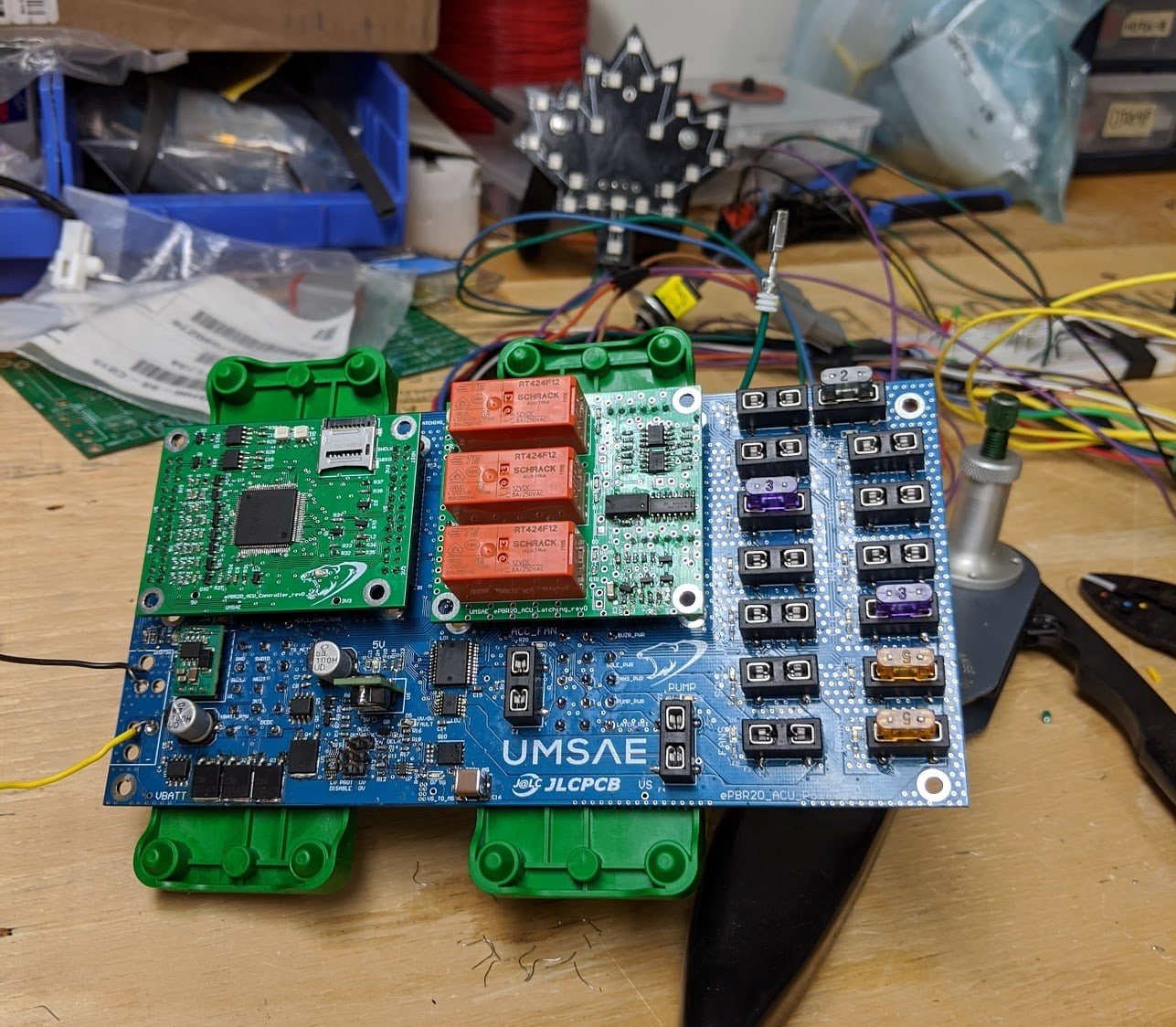
The ePBR25 ACU is comprised of 3 main PCBs:
The Low Voltage Board (LVB) fuses and distributes all the LV Power for the vehicle. It also pulls all the connections from the outside world into the ACU and distributes the signals to the other boards.
The Accumulator Control Board (ACB) or Controller Board, contains an STM32F446 microcontroller that controls the opening of the AIRs and turns on devices such as the fans, pump, and the ready-to-drive buzzer. Historically, the ACB also controlled charging, however, a separate charging PCB is being utilized to charge the accumulator this year.
The Latching Board contains the controls for the latching components of the safety loop. This includes the Insulation Monitoring Device (IMD), Accumulator Management System (AMS), and Brake System Plausibility Device (BSPD), which open the safety loop if a fault is detected. This board also contains the logic that controls the Tractive System Active Light.
The Vehicle Control Board (VCB) is the main PCB of the VCU, with its main functions being the Acceleration Pedal Plausibility Sensor, brake pressure and the dashboard. The VCB also contains an STM32F446 microcontroller. The VCB uses two CAN buses to communicate with the rest of the car behind the firewall. The microcontroller reads data from the APPS and communicates with the motor controller and ACU. The VCB also provides power for the dashboard LEDS and buttons.
The dashboard contains 3 fault LEDs for the IMD, AMS, and BSPD, and these signals go through the firewall to the ACU for latching purposes.
For the past 5 years, we have sourced our PCBs through JLC PCB. As designs for the car change often, we need a supplier who can react to our needs and supply PCBs on short notice so we can get back to testing and racing. JLC PCBs are of high quality and solid construction. They arrive quickly and are always made with precision. Our parts and components fit properly onto the boards the first time, every time, and these PCBs have always helped our team reach new heights in our competitions. We are grateful for the support of JLC in the production of our race car!
